Seismic Performance of an I-Girder to Inverted-Tee Bent Cap Connection
Sponsor: California Department of Transportation
29 February, 2008 to 14 February, 2010
System Test
Background:
Integral column and cap beam systems for bridges using precast concrete girders have several advantages over integral and non-integral structures consisting of steel girders or cast-in-place concrete. However, the use of precast concrete girders for the design of earthquake -resistant bridges in the US is limited due to the lack of research and design information regarding the cap beam connection to the girders. The research detailed here investigated the seismic design of a bridge system utilizing a reinforced concrete column integrally connected to a concrete inverted-tee cap beam supporting I-shaped precast concrete girders. The investigation included finite element and grillage analyses and experimental testing of a 50% scale test unit.
Objectives:
Investigate the behavior of the connections between concrete girders and an inverted-tee cap beam.
Investigate the overall seismic behavior of an integral bridge pier system consisting of a concrete column, I-shaped precast concrete girders, and an inverted-tee concrete cap beam.
Investigate the behavior of the connection between the concrete column and
the inverted-tee cap beam.
Test both an as-built Caltrans and an improved girder-to-cap connection to ensure that they pro- vide sufficient shear and moment capacity to enable successful formation of a plastic hinge at the column top.
Experimentally validate and document the girder- to-cap connections.
Develop suitable design recommendations and specifications along with a measure of improvement for girder-to- cap connections.
Investigate the shear force transfer in the cap-to-girder connection to verify that this transfer is not compromised if the connection experiences deterioration.
Inverted Tee Bent Cap Connections Concept:
The connection of an inverted-tee pier cap to I-shaped girders is well-suited for accelerated bridge construction (ABC) methods, as precast girders can be placed in the field on the ledge of the inverted-tee without any false work. Successful improvement and testing of the specific connection between precast I-girders and an inverted-tee bent cap could lead to use of precast components in future bridges.
"Improved" connection: an enhancement of a connection commonly used by Caltrans was accomplished by using a grouted, unstressed post-tensioning strand connecting each of the girders to the pier cap. In a new bridge design, this unstressed strand would run continuously through both girders on either side of the pier cap. However, since the right side of the test unit's pier cap was intended to be the "as-built" connection for comparison, the unstressed strand was terminated at the right face of the pier cap and was not continued into the as-built side.
Columns with this connection have, to date, been designed assuming a pin support at the column top adjacent to the cap. Having a pin support at the column-to-cap connection is not desirable for seismic regions, because it prevents the possibility of forming a plastic hinge at the column top, thereby increasing the foundation costs and making the precast option cost prohibitive. Although assumed to be pin connections in previous designs, this project showed that even currently existing as-built inverted-tee connections would behave more like fixed connections than pinned connections.
Methodology:
The test unit consisted of a single column with an inverted-tee cap beam and five I-girders overlaid with a deck on each side. In order to test both the as- built cap-to-girder connection as well as the proposed improved connection, one side of the cap beam was constructed using the as-built details while the other side was constructed using the improved connection details. Since a majority of the negative moment contribution would be provided through the deck, both connections were expected to behave similarly when combined as such into one superstructure. Therefore, based on whether the superstructure was pushed or pulled horizontally, it was possible to isolate the behavior of only 1 of the connections under either negative moment or positive moment loading.
The experiment was divided into 2 main phases. Phase 1 investigated the sufficiency of the cap-to-girder connection in having adequate capacity to develop the plastic hinge in the column under horizontal loading. Phase 2 used vertical loads at the girder ends to fully exercise the cap-to- girder connections and to investigate the ultimate capacity of the connections in order to validate the current design approach, which assumes that the as-built connection will degrade to a pin condition.
Major Findings:
Contrary to current design assumptions, the as-built connection of the inverted-tee pier cap to the precast I-shaped girder behaved as a fully continuous connection in- stead of a pinned connection.
The improved cap-to- girder connection per- formed as expected, ensuring fully continuous behavior under both positive and negative moments.
Both the as-built and improved connections successfully transferred shear forces from the superstructure into the cap beam.
The inverted-tee pier cap detail can be used in an integral connection design to develop a plastic hinge in the column top; thus, the inverted-tee pier cap is a great way to implement precast concrete girders in seismic areas and promote ABC construction.
The improved connection achieves the design goals of an integral connection.
Connection Tests
Background:
The system test provided overall superstructure behavior and column response of a single column bent. It showed that the superstructure would remain fixed under high seismic loads and also allow a second plastic hinge to develop at the top of the bridge column. Following the system test, the connection tests were developed to further quantify the response of specific girder to cap connections as well as provide the designer with multiple options to facilitate positive moment resistance. The objectives of this phase of the study are outlined below:
Provide multiple precast girder to cap connection details that facilitate integral bridge superstructures by providing adequate positive moment and shear resistance.
Accommodate multiple bridge span lengths up to a maximum span length of 150 ft through the use of both precast, pretensioned I-girder and bulb-tee girders.
Investigate seismic response of connections between precast concrete girders and bent cap with consideration given to both horizontal and vertical acceleration effects.
Develop analytical tools to aid in the design of positive moment connections.
Experimentally validate and document the performance of the girder to cap connections.
Formulate suitable recommendations to implement the new connections in high seismic regions.
Connection Details:
A total of four different connection concepts and six different details have been investigated. Details of each connection are provided below.
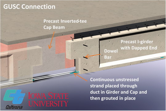
Grouted Unstressed Strand Connection:
Precast I-girder with dapped end and precast inverted-tee bent cap
Unstressed strands placed through ducts in girder and cap and then grouted in place
Three dowel bars placed transversely through the web of girder
Diaphragm and deck poured to secure girder to cap and encase dowel bars
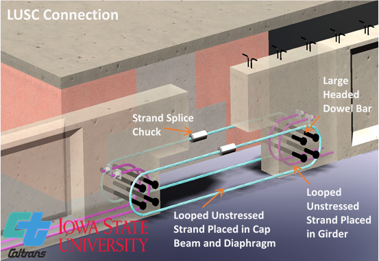
Looped Unstressed Strand Connection (LUSC):
Precast I-girder with dapped end and precast inverted-tee bent cap
Looped unstressed strands placed in cap beam and girder
Cap beam looped strands extend from cap into diaphragm region
Large-diameter dowel bars placed transversely through looped strands in girder and cap beam
Diaphragm and deck poured to secure girder to cap and encase cap looped strands and dowel bars
Extended Strand Bent with Free End (ESBF):
Precast bulb-tee girder with cast-in-place bent cap
Some of the girder prestressing strands are extended from end of girder and bent at 90 degrees with no anchorage
Dowel bars placed transversely through web of girder
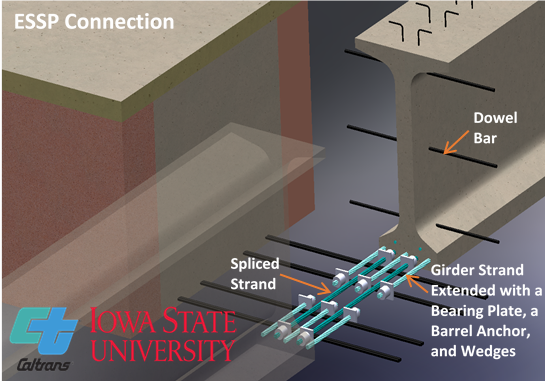
End Plate (ESSP):
Precast bulb-tee girder with cast-in-place bent cap
Some girder prestressing strands are extended from the end of the girder a short distance and then spliced with strand ties
Extended strands and strand ties are anchored with plates and anchor chucks
Dowel bars placed transversely through web of girder
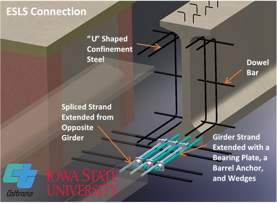
Extended Strand Lapped Splice (ESLS):
Precast bulb-tee girder with cast-in-place bent cap
Some girder prestressing strands are extended and lapped with extended strands from opposite girder
All extended strands are anchored with plates and anchor chucks
Dowel bars placed transversely through web of girder
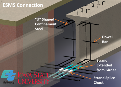
Extended Strand Mechanical Splice (ESMS):
Precast bulb-tee girder with cast-in-place bent cap
Some girder prestressing strands are extended and connected to extended strands from opposite girder with a mechanical splice chuck
Dowel bars placed transversely through web of girder